Bridge equipments on a merchant ship
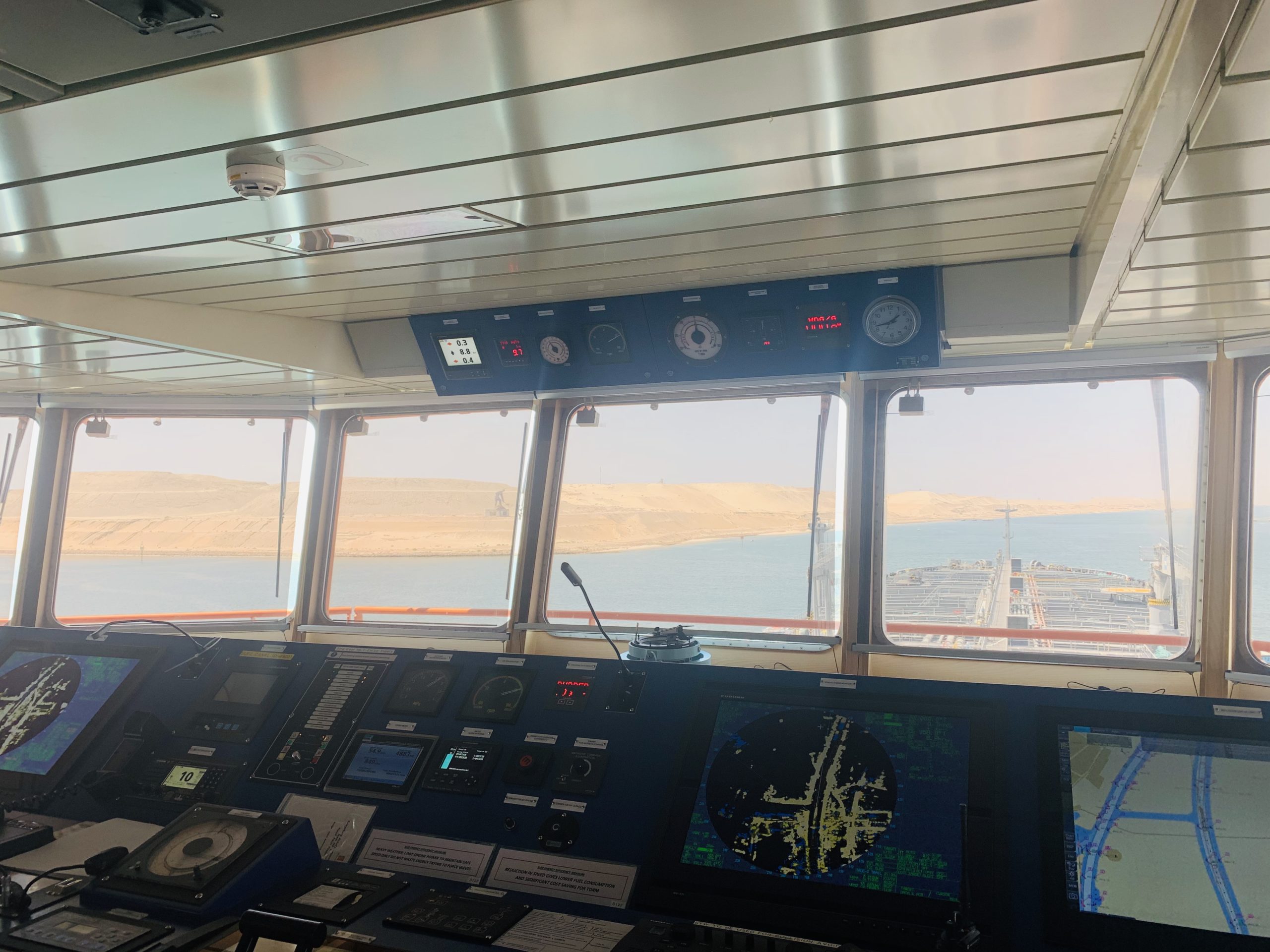
A vessel is controlled and navigated from the bridge. Thus for the safety of the vessel & crew, and for the record keeping there are various equipments provided on the bridge of a merchant ship. The bridge equipments and their purpose is given in the content below.
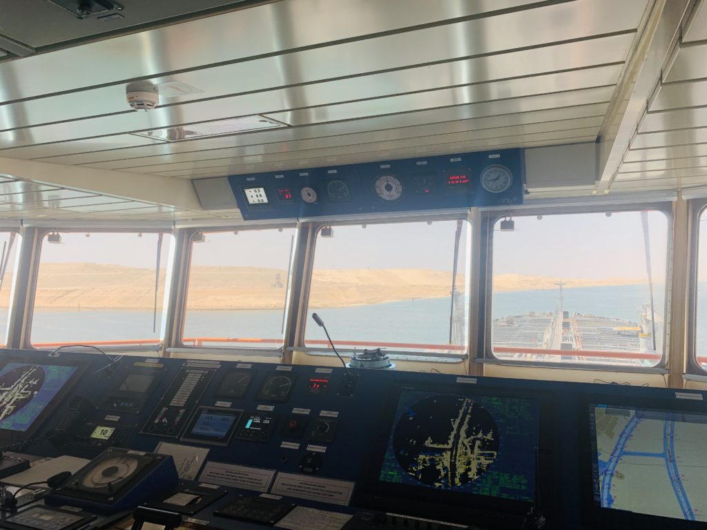
When a ship is navigated, it needs various bridge equipments to navigate the vessel safety in call conditions of traffic, visibility and waters.
Thus in order to acquired and track other ships, monitor the vessel’s progress, check the depth below the ship, communicate with other ships and with shore, send and receive messages to ship and shore and broadcast and receive the required data vessels are provided with these equipments.
The bridge equipments are used for various purposes. Some of the bridge equipments like VHF & MF/HF and SAT-C are used for communication, while other bridge equipments like Radars and Speed logs are used for collision avoidance.
The bridge equipments like ECDIS are used for anti grounding.
Following are the basic bridge equipments and controls on a bridge of every merchant vessel.
Table of contents (Bridge Equipments)
- GPS
- ECDIS
- RADAR
- AIS
- Echo sounder
- Speed log
- VHF & MF/HF
- SAT-C
- Autopilot system
- BNWAS
- VDR or SVDR
- Off course alarm systems
- Gyro compass & Magnetic compass
- Course recorder
- Steering system
1.GPS
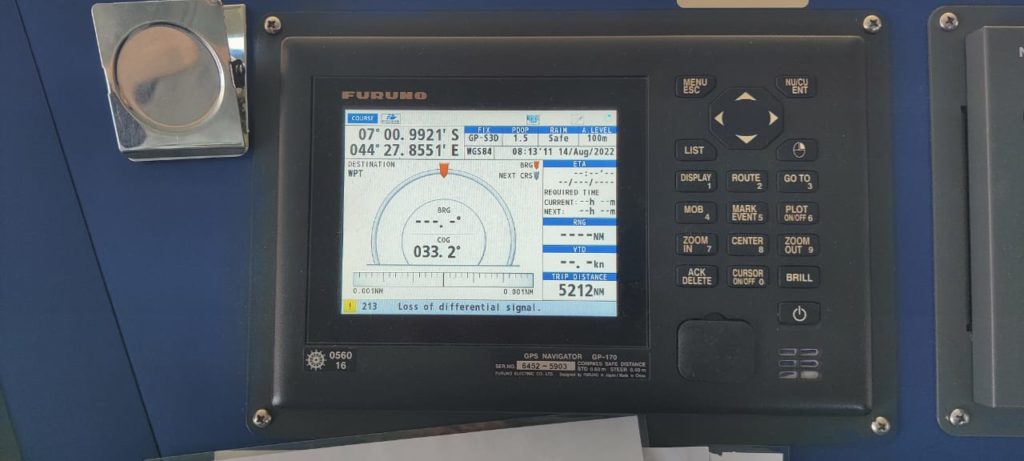
This is nothing new now a days. Today all the smartphones come with GPS and we all know about how to use it. The accuracy of the GPS in the smartphones is so much that it can take you anywhere in the world without any significant error.
Same way, onboard ships we are provided with the GPS in the bridge equipments. The only difference is that we are provided with a separate unit of GPS on bridge, which gives feed to all other designated equipment’s onboard.
GPS stands for Global Positioning system. GPS Provides mariners the fastest and the most accurate ways to determine its current location, the speed through the ground.
Basically GPS consists of three segments called the space segments(consisting satellites), the control segment(control stations) and the user segment.
While the initial two segments are used and operated by the US Airforce, the user segments are us, the users.
The space segments consists of satellites transmitting radio signals to the users.
The control segment consists of ground stations, which track the GPS Satelites, monitors their signals and send commands and data to the satellite network.
While the GPS receivers on ships calculate the position by satellite ranging. Which simply means that the receiver received the signal from the satellite and then calculates the distance between the satellite and the receiver.
Now that the receiver has distance from one satellite. And the receiver is receiving signals from 3-4 GPS satelites at the same time.
This way the receiver calculates the range from all these satelites and thus by the intersection of the range spheres we get the 3D position of the vessel on the earth.
2. ECDIS
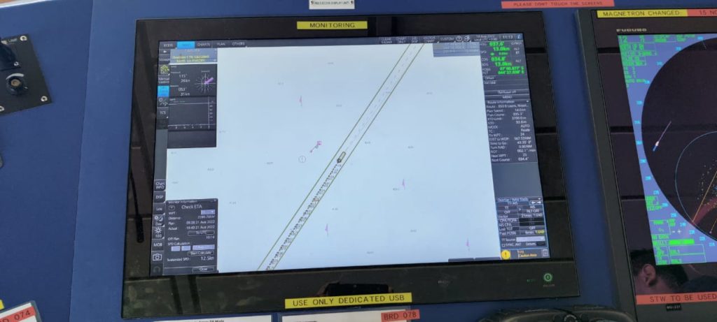
ECDIS stand for electronic charts display and information system. Which means the charts and the information associated with them are stored and displayed to us in digital format.
While the ECDIS is an anti-grounding tool which is mainly used to monitor the progress of the vessel along the route.
ECDIS receives feed from minimum 3 of the bridge equipments. which are the GPS, LOG and the gyro.
While the GPS provides the position, gyro is providing the heading of the ship. While the log provides ECDIS the speed of the vessel.
Once we have prepared the passage plan and laid the courses on ECDIS, the position of the vessel is being displayed on the ECDIS.
What we need to do is we have to monitor the progress of the vessel and confirm the position of the vessel by various available means wherever available.
In the olden times the mariners used to navigate with the help of paper charts. The papers charts had the required information indication the depths of the area covered.
The biggest disadvantage of the charts was that the vessel had to maintain a large foils of the charts. And the inventory of the charts had to be maintained up to date.
And when the vessel used to receive the weekly chart corrections, all the charts had to corrected manually. All the charts had to be corrected manually, which was time consuming as well as there were chances of human error.
After the introduction of ECDIS, The chances of human error have been minimised, while on the other hand it is time saving too.
But now a days when the vessel receives the weekly charts correction, the charts on the ECDIS can be corrected in a fraction of minute.
3. RADAR
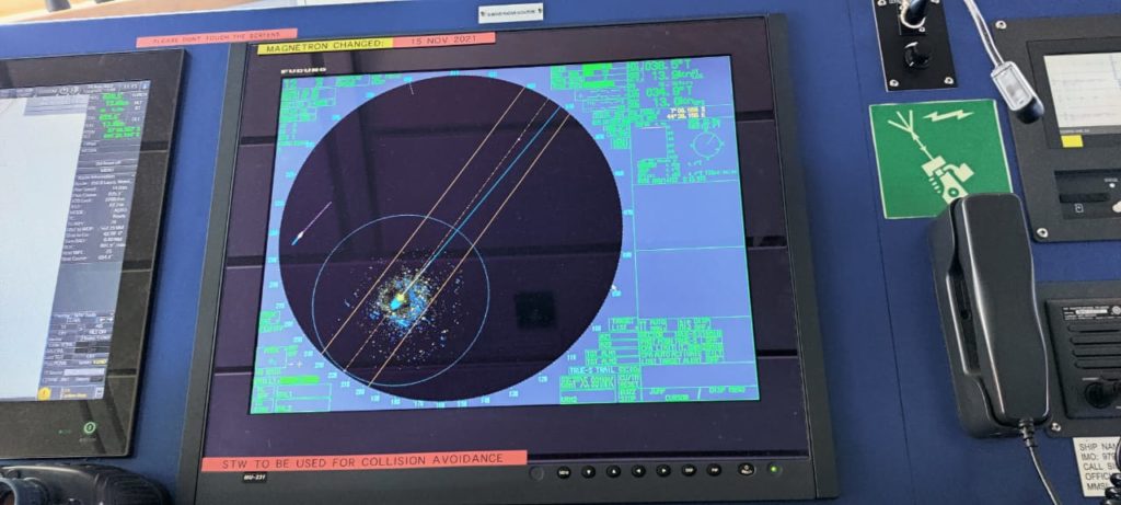
Radar is provided on ships for the purpose of collision avoidance. Radar basically used as an assistance to the watchkeeper for the safe navigation and the collision avoidance by providing the the positions of the other vessels, land, conspicuous navigational hazards and other objects.
Radar consists of four units named the scanner unit, receiver unit, scanner unit and the display unit.
While the transmitter transmits the signals(electro magnetic energy pulses) through the scanner.
These pulses strikes the target and comes back to the receiver. The receiver then processes these signals and shows them on the display unit as blips.
The size of the blips depends upon the size of the target. The bigger the target, the bigger the blip will be.
There are two kinds of radar basis on the wavelength. Wavelength of X band radar is about 3 cm (9.2-9.5 GHz). While the wavelength of S-Band radar is about 10 cm(2.9-3.1GHz).
Usually on each ship X-Band radar is provided because it is good in detecting nearby and smaller objects. One more thing is that it is useful in case of search and rescue, as only X-Band radar can detect the SART signals.
While the S-Band radar is good for long range detection. Thus if two radars are fitted on a ship. One of them might be S-Band and the other one should be X-Band radar.
4. AIS
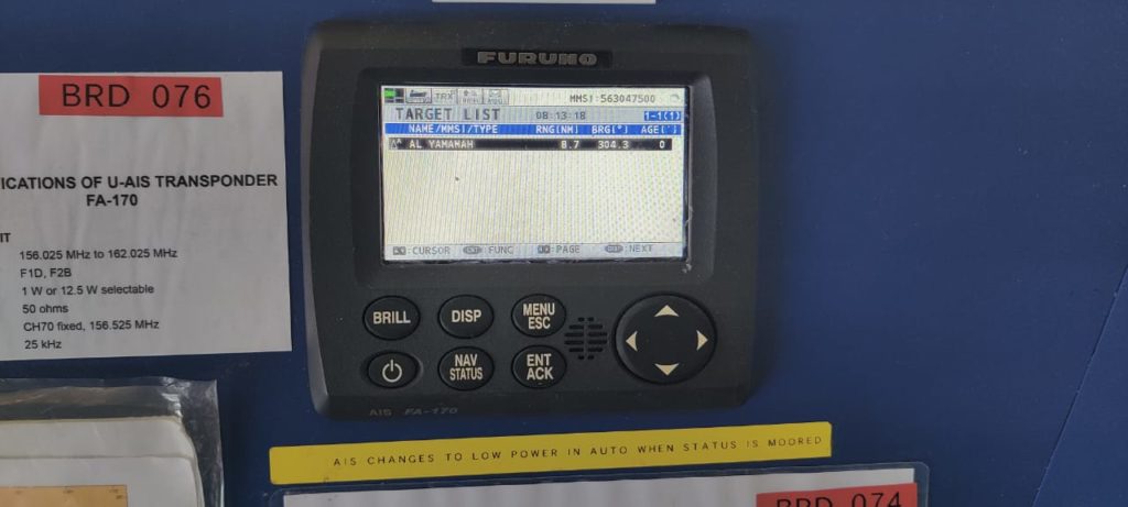
AIS stands for Automatic Identification System. This is basically a broadcast system, which broadcasts the fed data to surrounding ships and other AIS receivers in the area including the VTS and other receivers.
While the other ships can use it just as an aid to navigation, the VTS uses AIS to acquired the vessel data and monitor it in their area.
The data broadcasted in the AIS is of three types. The types are-
- Static data
- Dynamic data
- Voyage related data
The static data contains the standard data which can not be changed by the operator.
The static data includes the Ships name and call sign, types of the ship, length and beam of the ship, imo number, location of the antenna and the MMSI number.
While the dynamic data is the data which is fed to it by other sensors. Which includes the position of the ship, heading of the ship and the course over ground.
The voyage related data is the data which has to be fed by the operator when there is any change in the data. The voyage data includes the fraught of the ship, destination and ETA and type of the cargo.
AIS works on the VHF frequency(channels 87B for ship to ship, and channel 88B for ship to shore). Which means there will be a VHF transmitter and two VHF receivers
The AIS works on the SOTDMA technology. Which stands for Self organising time division multiple access.
The AIS slot frame is provided which consists of 2250 slots available in one minute of time frame. So our AIS will scan for the available slot in the slot frame and the transmitter will transmit the data within the chosen time slot.
Since this all works in automation, thus this is called self organising TDMA.
5. Echo sounder
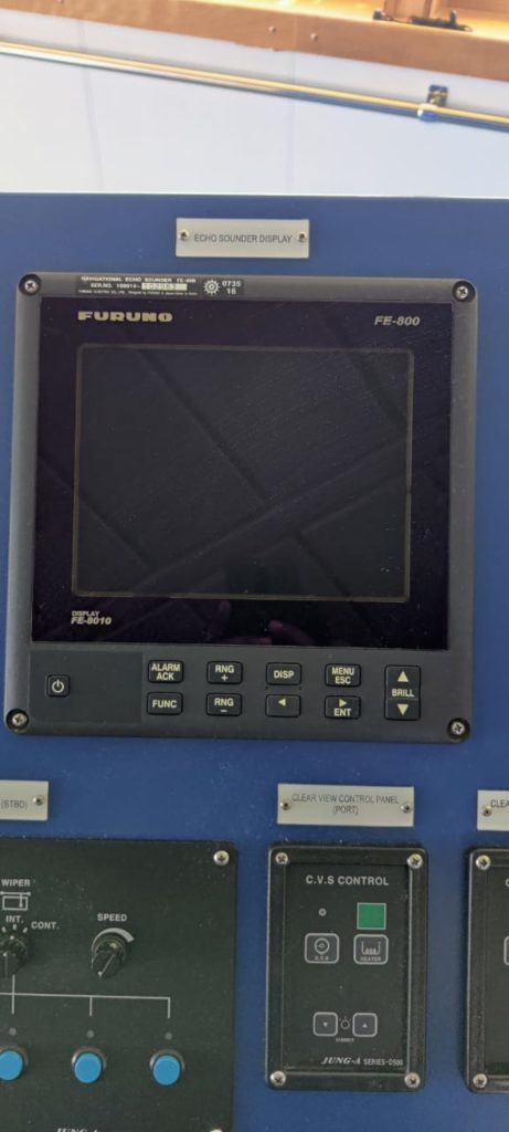
Since the vessel sails in water, the depth below is invisible to us. Thus there should be some equipment which shows us the depth below our vessel so that we can navigate safely without danger of running aground.
However the depths of the water are already given on the navigational chart, but there should be some means to cross verify that the depths given are correct.
Thus the Echo sounder is provided onboard ships to give the depth under the keel of the ship. This is the most important bridge equipments for anti grounding purpose.
Echo sounder can be of various kinds and brands but they all work on the similar principal.
Which means that the transducer transmits the sound/acoustic waves towards the sea bottom, which then strikes the sea bed and returns back to the receiver.
The velocity of these waves are equal to the velocity of light. Thus the time taken from the transducer to the receiver is known.
Thus the depth is calculated automatically by the formula distance=velocity x time/2.
The depth is then shown to us either by digital means or it is being plotted automatically on a paper chart, which can be used to see the depth.
6. Speed log
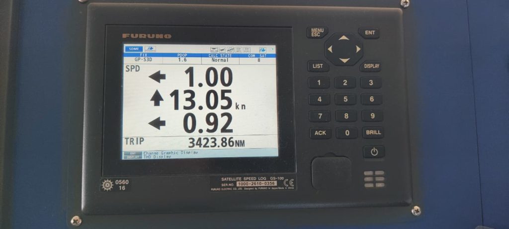
Speed log is provided in bridge equipments to measure the speed of the ship. The speed logs provided on ships can be of various types. Which includes the Doppler log, the electromagnetic log and a few other types of logs.
The Doppler log is most commonly found on the merchant ships. Which works on the Doppler shift in frequency measurement.
Which means that a pulse of a known frequency is transmitted to the seabed, which is then reflected back to the ship.
Then we know the difference between the transmitted and the received frequency. The difference in the transmitted and the received frequency is proportional to the speed of the ship.
The Doppler log shows both speeds Speed over ground and speed through water.
When the depth below keel is less than 200m then the pulses strikes the seabed and returns to the transducer. The speed calculated then is called speed over ground.
While on the other hand if the depth is more than 200m then the pulses return from water of 10m to 30m depth. The speed calculated will then be speed through water.
7. VHF & MF/HF
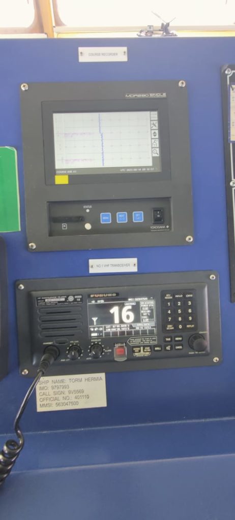
VHF and MF/HF are the bridge equipments which are used for the communication purpose.
While VHF can be used for the shorter range of up to 50 nautical miles, the MF/HF can be used for larger range. The MF/HF can be easily used up to 200 nautical miles.
The VHF and MF/HF are primarily used to make ship to ship or ship to shore calls.
These bridge equipments can also be used for receiving and transmitting and receiving messages, sending routine, safety, urgency and distress messages.
While the DSC(digital selective calling) facility is provided in these equipments in order to establish the initial contact between ship to ship, ship to shore or shore to ship.
DSC is used to transfer the information digitally to the other ships or to the coastal station.
8. SAT-C
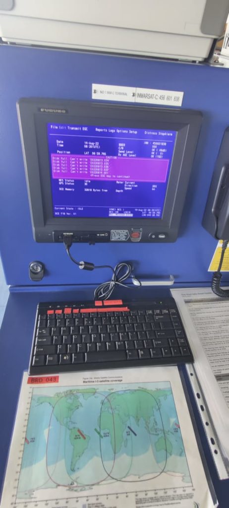
SAT-C is installed on bridge in order to receive maritime safety information, distress, urgency information as well as transfer the emails to any email address.
SAT-C is fully compliant with the GMDSS. SAT-C equipments also contains a designated distress button to send the distress directly from these bridge equipments.
Thus SAT-C provides tow way messaging, distress calling, data reporting and EGC services.
SAT-C is used to send messages from ship to ship, ship to shore and shore to ship facilities.
9. Autopilot system
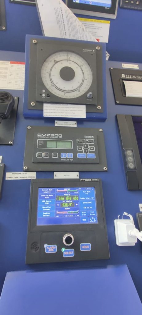
The autopilot system is used to steer the vessel in autopilot without the need of any manual steering in open seas.
When the vessel is in confined or pilotage waters, it has to be steered manually. While on the other hand when the vessel is in open seas it becomes difficult to steer it manually for so prolonged times.
Thus the autopilot system is provided so that the vessel can be steered in auto system. The course to be steered is taken from the gyro or the magnetic compass on ship.
The course to be steered is selected by the operator and then it can be changed by the course selector knob.
While the heading is maintained by the autopilot system, the course alterations can also be carried out by the autopilot system.
There are various types of settings in autopilot system which has to be changed by a trained operator only. The settings include the rudder settings, the weather settings and the other helm settings including the rudder control, counter rudder, rate of turn settings and PID controls.
10. BNWAS
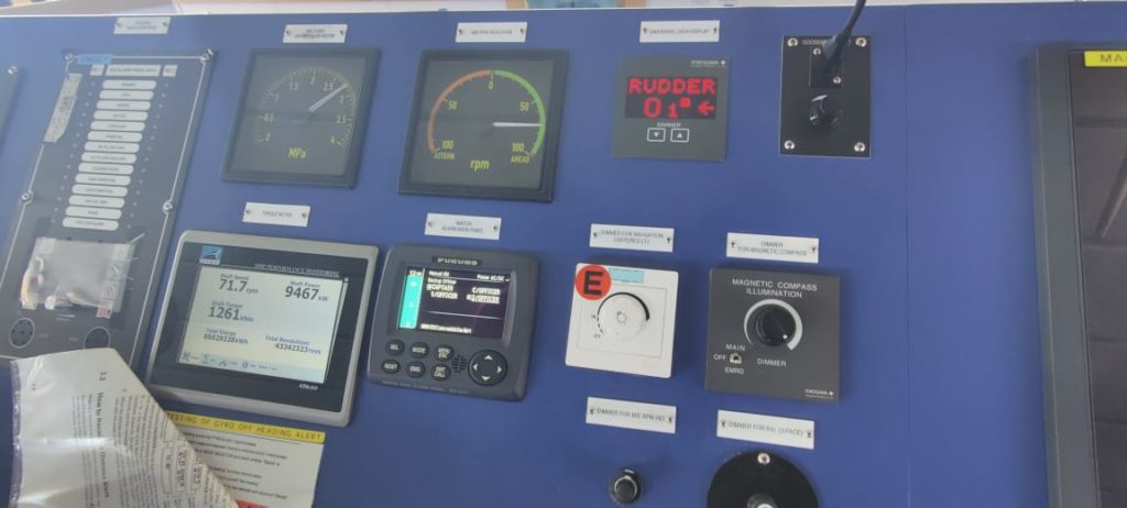
BNWAS stands for bridge watch navigation alarm system. Which is installed for the safety of the vessel and the crew.
When a watch keeper or OOW is alone on watch and something happens to him. Since he was alone on the watch and now he is unable to maintain lookout or take any avoiding actions for the vessel.
Thus he is unfit to carry out the duties but if the crew below the bridge are not aware the situation and some accident occurs, it can be life threatening to everyone.
So in order to maintain the safety of the vessel and the crew, the bridge equipments called BNWAS was installed on vessels so that when the watch keeper is ill or tired ir unfit due to some other reason, then other backup officers/ master can be alerted by means of an alarm system.
The alarm system alerts the OOW first and the OOW can reset the alarm. But if the OOW is unable to reset the alarm on bridge then it alerts the other designated officer/master in his cabin.
Thus the master or the backup officer can reach on bridge and handle the situation.
BNWAS has to be ON and operational whenever the heading and track control system of the vessel is in engaged. The BNWAS also has to be operational when the vessel is at anchor.
There is motion sensor also fitted to reset the BNWAS alarm but that depends on company or the flag of the ship if they allow the motion sensor is to be used.
11. VDR and SVDR
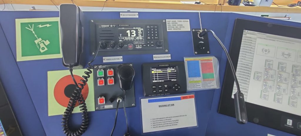
When the vessel is at sea or in port and some incident or accident happens, then there should be some equipments which stores all the data for the duration of the accident. So that the data can be used for incident investigation.
Thus VDR was installed on ships so that it collects and records all the data in a memory drive which can be accessed if required. The only thing is that the data has to be saved in a time limit so that it can be saved in a separate drive and be accessed later.
It should maintain the data for a minimum of 12 hours and should be accessible once saved.
VDR stands for the Voyage Data Recorder. Which means that it records and maintains all the data required by the regulations.
The data feed is taken from the associated equipments including the Radar picture, Echo sounder, bridge audio, VHF audio, ship’s heading and speed, engine order and response, rudder Oder and response, wind speed and direction, date, time and position.
While the VDR on ships can be of two types- which are
-VDR(Voyage data recorder)
-SVDR(Simplified voyage data recorder)
The only difference between them is the amount of data they store. While VDR stores more data, the SVDR only stores the data required by the regulations.
SVDR stores data like bridge and VHF audio, date, time and position, ships heading, ship speed and radar picture.
12. Off course alarm system
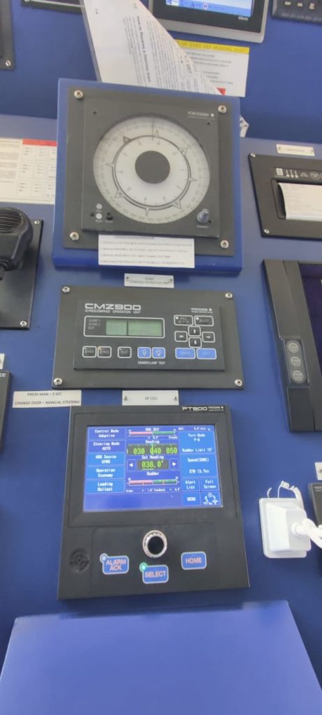
Off course alarm system is associated with the auto pilot system. Which will give and audio and visual alarm when there is deviation of the set course from the present course.
Suppose the ship is on autopilot and we have set heading of 050 deg. And the off course alarm setting is 5 deg. And due to some external or internal factors the ship’s heading changes by more than 5 degree.
If the ship’s heading crosses 055 degree or 045 degree then the off course alarm will sound and notify the officer on watch.
The off course alarm system thus acts as an assistance to the OOW to see if the ship is sailing on the preset course.
13. Gyro Compass and Magnetic compass
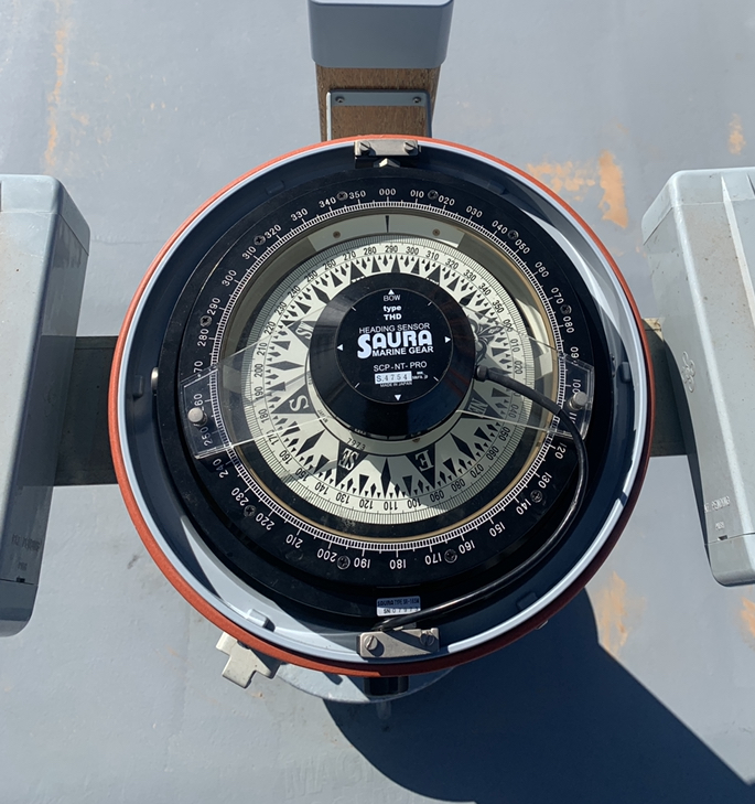
As explained in the earlier posts, the gyro and magnetic compass are installed in bridge equipments in order to provide the ships gyro and magnetic heading.
While the gyro heading is indepedent of the magnetism of the ship. The magnetic heading of the ship varies and thus has to be corrected according to the position of the ship on this earth.
Gyro compass is used to determine the heading of the ship by non magnetic means. The heading should be clearly readable by the helmsman and the feed should be provided to the other equipments required.
Gyro compass can provide bearings over an arc of 360 degree on horizon.
The Magnetic compass contains a magnetic needle which aligns itself in the magnetic field of the earth and provides us the magnetic heading of the vessel.
The magnetic heading depends on the position of the ship, ship’s structure and the position of the magnetic compass on the ship.
14. Course recorder

This bridge equipment is used to record the course steered by the vessel automatically. The course recorded can be on paper or it can be recorded by digital means.
The reason to record is that it acts as an evidence about that was the course steered by the vessel.
Course recorder is mainly useful in case there is some accident or grounding occurred. Then the course steered can be checked and inbvestigated.
The course recorder records the course as well as it has the date and time stamp at frequent intervals.
15. Steering system
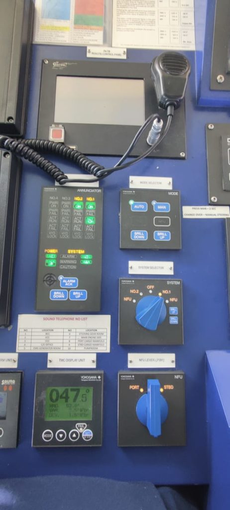
It is the system provided on bridge to control and change the course steered by the vessel. The steering system includes the rudder actuators, steering gear power unit, tiller and other associated machinery.
While all the other machineries are provided in the steering gear room, the steering gear control and the wheel are provided on the navigation bridge.
As in the normal conditions, the vessel is steered from the bridge thus the steering controls, steering motors start and stop controls, steering wheel and the steering related failure alarms are provided on the navigation bridge.
The steering helm can be given from 0 to 35 deg on port and stbd side. When the helm is given from the bridge same order is passed to the rudder by electrical and mechanical means.
Then the rudder is moved by the ordered angle and the same is shown on the rudder angle indication on the bridge.
Pingback: AIS types, construction and purpose - BloggingSailor
Pingback: Speed log- how it measures speed of vessel - BloggingSailor
Pingback: Radar on ships- types, principle and purpose - BloggingSailor
It’s really a great and useful piece of information. I am glad that you simply shared
this helpful information with us. Please keep
us informed like this. Thank you for sharing.