What is Inert gas system
The inert gas system means the inert gas plant, inert gas distribution system with means for preventing back flow of cargo gases into the machinery spaces/engine room.
As the name indicates, inert gas system produces the inert gas, which is then introduced into the cargo system in order to control the tank atmosphere.
So once you reach at the end of this article, you will be able to find the answers of the following questions:
What is an inert gas?
Why is inert gas needed on oil tankers?
What is inerting, purging and gas freeing?
What are the components of the inert gas?
How do we produce the inert gas?
Difference between inerting and purging.
Difference between PV Valve and PV Breaker.
How is inert gas actually used?
So lets discuss the table of the contents we will be going through-
Table of contents:-
Components of the inert gas system
Purpose of the inert gas & inert gas system
Inerting, Purging and gas freeing and procedure
What is an inert gas
Inert gas in nothing but just a composition of gases, which contains oxygen and other gases in such a ratio that it can make any atmosphere inert.
when we say inert gas in this article, we are talking about the inert gas onboard ships.
In inert gas, the amount of oxygen is kept low so that it does not support combustion of hydrocarbons.
Now let’s see, about why do we need to reduce the oxygen level of the tanks. And why the oxygen level affects the hydrocarbon level.
As we have discussed that the in order for the fire to take place at any given time, three components are required to be present.
These three components complete the three sides of a fire triangle.
Then there is Flammability diagram provided, which provides us info about what are the safe conditions for any cargo operation or other operation on tanker related to the contact of hydrocarbons.
Components of inert gas system
Inert gas system need following components in order to generate and deliver the inert gas on deck.
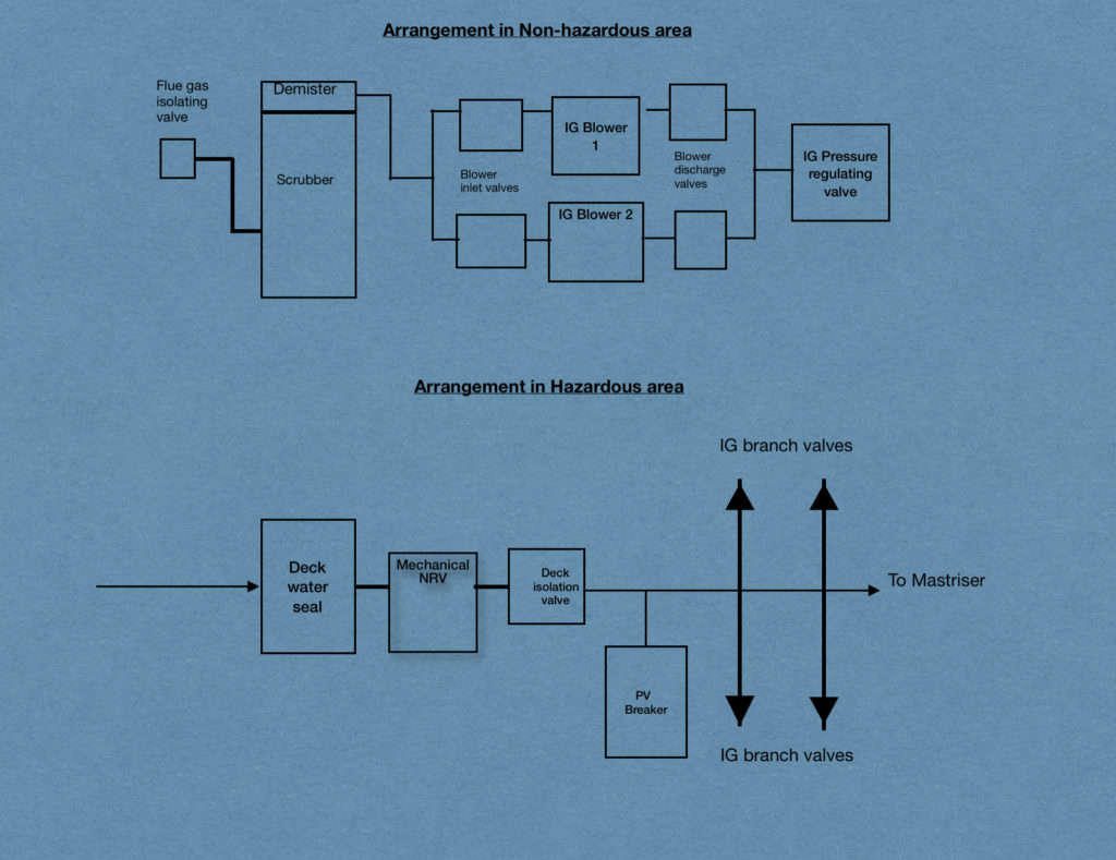
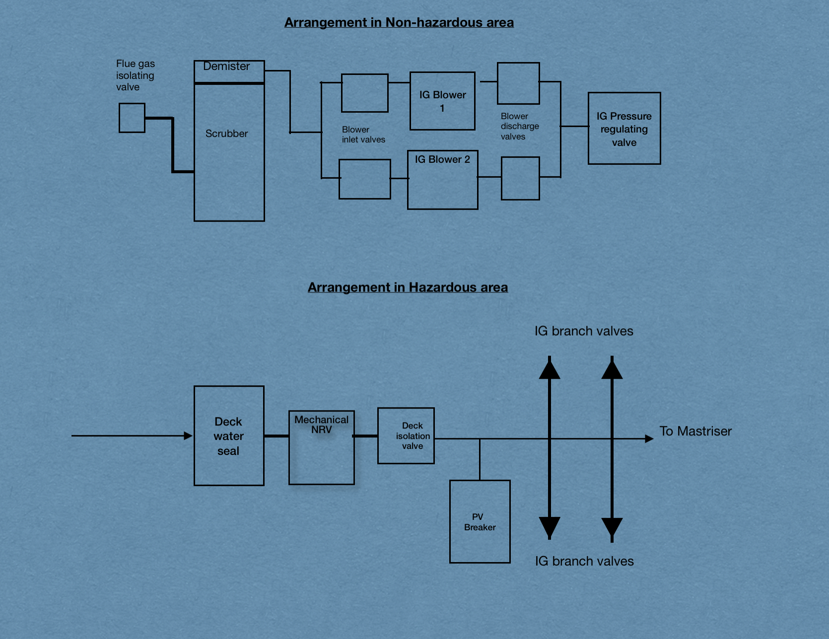
1. Uptake Valve & Flue gas isolation valves
The uptake valve is located at the boiler and is used to vent out the dirty flue gases generated from the boiler.
Then there is flue gases isolation valve, which is located after the boiler uptake valve.
When we open this valve, the flue gases are taken to the scrubber for the purpose of cooling it down and removing the impurities.
2. Scrubber
Scrubber is a tower built next to the boiler uptake for the purpose of cooling the flue gases coming from the boiler. Sea water is run continuously during the operation in order to cool the hot gases coming in.
Then there are demister pads fitted inside and on the top part of the scrubber.
The arrangement is made in such a way that the flue gases enter the scrubber from the bottom, And the sea water is showered onto it thus cooling it.
Now what happens is that these flue gases ascend upwards and pass through the demister.
The purpose of the demister is to remove the sulphur and other impurities from the flue gases. That’s why the demister is fitted with the pads which are called the demister pads.
The purpose of the demister is to remove the sulphur and other impurities from the flue gases. That’s why the demister is fitted with the pads which are called the demister pads.
3. IG Blowers
The blowers are two in numbers and either one can be run to provide the required rate of inert gas to the cargo tanks on deck
The requirement is that both blowers when run together, should be able to deliver the inert gas on the cargo tanks at a rate of at least 125% of the total discharge rate of the ship.
But on mostly ships we will come across where the individual capacity of a IG blower is 125% of the total discharge capacity of the ship. It’s because if any one of the IG blower is not working, the other blower is able to provide the IG at max required rate, so that the discharge rate is not compromised.
4. Inert gas pressure regulating valve
Inert gas pressure regulating valve: Then there is last component of the IG system inside the engine room.
Pressure regulating valve regulates and controls the flow of the flue gases to the cargo tanks.
These were the main parts of the inert gas system inside the engine room.
Now comes the deck part of the inert gas system. The deck part is called the hazardous area because of the presence of various cargo vapours.
IG system components in hazardous area
The deck part of the inert gas system contains the Vent valve, the deck water seal, non return valve, deck isolation valve, PV breaker and the tank IG valves.
While the vent valve is provided just before the deck water seal, in order to vent the gas when there is an emergency and the plant has shut down.
Then there is a mechanical non return valve located just forward of the deck water seal in order to prevent the back flow of the cargo vapours from the cargo tanks to the engine room.
This is the requirement set by IMO for the safety of the vessel.
As the cargo vapours flowing back from the engine room to the deck will be containing sufficient amount of hydrocarbons.
And we have already discussed the flammability diagram in the other article. That once these hydrocarbons reach back to the engine room and mixes with the air. Then there are very much chances that there might be an explosion.
The explosion might easily take place inside engine room because there are plenty of hot surfaces inside, and if there are hydrocarbon gases and the oxygen is present then the chances are very likely that there will be an explosion or fire inside engine room.
So in order to control the back flow of these gases, there is a mechanical non return valve provided just ahead of the deck water seal. The no return valve (called NRV) acts as the first point barrier in case of back flow.
The second barrier is the deck water seal itself.
Because the non return valve is a mechanical valve and might not be efficient enough to stop completely the back flow. So the deck water seal, in which the seal made of water mainly acts as the barrier acts as the most efficient barrier.
Once the inert gas passes through the inert gas isolation valve, it leads to the individual cargo tanks.
The individual cargo tanks are connected with the IG line and provided with the individual isolation valves.
So in case we want to isolate the cargo tank from the inert gas system, it can easily be isolated by closing the branch IG valve for that tank.
While there is one more safety device provided on deck, called the PV Breaker.
PV Breaker is filled up with a mixture of fresh water and glycol. Glycol is added with water in order to make the mixture anti freezing.
So the PV Breaker lifts up in case the pressure inside the IG line increases.
If the pressure in the IG line exceed above designated pressure, the liquid filled up inside the PV Breaker blows away and the pressure is released.
While on the other hand, if the vacuum inside the IG line or the cargo tanks increases below the design set pressure, the liquid will be sucked inside the cargo tanks and the IG main line.
Thus it will prevent the cargo tanks and the IG line from getting ruptured due to excess vacuum.
So this was the basic flow of the inert gas from the boiler uptake to the cargo tanks.
We will revise it once more for clarification.
Flue gases are generated inside the boiler. Then through the boiler uptake they are taken to the scrubber.
Scrubber removes the impurities including sulphur from the flue gases and cools the flue gases down.
Now the flue gases pass through the demister, where all the remaining impurities are removed.
Thus now the flue gases are now inert as per our requirement and compatible to be sent to the deck and cargo tank system.
So the inert gas is sent to the IG blowers, which sends the inert gas to the deck going through the deck water seal.

Purpose of inert gas system
The purpose of the inert gas system has already been covered earlier in this article.
The purpose of the inert gas system is to generate and supply the inert gas to the cargo tanks, so that the atmosphere inside the cargo tanks to reduce the hydrocarbon and the oxygen level inside the tanks.
Inerting, Purging and Gas freeing
Inerting, purging and gas freeing are three terminologies used mainly during the tank cleaning operations.
Inerting
Inerting is the process of making the atmosphere of any tank inert.
Inerting is mostly used to make the cargo tanks atmosphere inert. While in some rare cases we might need to inert other tanks also, but those cases happen very rarely.
For example if there is some leakage from a cargo tank to the adjecent ballast tank, then the hydrocarbon content inside the ballast tank increases to unsafe level.
Thus in order to make it suitable for entry we will have to make the atmosphere inert and then make it gas free.
So let’s talk about inerting a cargo tank by means of Inert gas.
Which simply means that if a tank atmosphere is having Oxygen content of more than 8%, then we have to reduce tha oxygen content and bring it below 8% in order to make it inert.
Thus in order to reduce the oxygen content, we introduce the inert gas to the desired cargo tank through the inert gas line.
While the inert gas is supplied to the tank continuously, we know that there is already a gas mixture inside the tank.
So it means that we have to replace the existing gas mixture with inert gas.
Thus in inerting process, we introduce the inert gas to a cargo tank and then we open a few openings(purge flaps/ PV Valves) for the diluted gas mixture to exit.
In the process the inert gas gets more and more diluted and after some time the gas mixture inside the cargo tank is at level where the oxygen content is below 8%.
Once the oxygen content is below 8%, it is unable to support any combustion and thus it is safe for the loading and carrying the cargo containing hydrocarbons.
Purging
This can be sometimes confusing, specially for cadets or new comers onboard.
As purging also requires inert gas and same procedure is followed in inerting and purging. So what is the difference between inerting and purging.
Actually purging is the process, which is used to reduce the HC content of any cargo tank which is already in inert condition.
When we read that Flammability diagram, we saw that if we put fresh air inside any cargo tank which is having Hydrocarbon rich atmosphere.
Then it will follow a path which passes through the flammable range, and thus there is risk of expolsion in the tank.
Suppose we have to make man entry for cleaning any cargo tank. And what we do is we have already washed the cargo tank by tank cleaning machines.
Now we have transferred that washing water to slop tanks and now we have to enter the tank in order to remove the remaining water and make the tank dry.
But the tank atmosphere contains oxygen below 8%. And we know it very well that for a person to survive, the oxygen content should be 20.9%.
So we have to insert the fresh air inside the tank and make it gas free in order to make it safe for man entry.
And suppose the HC content was above something like 8% by volume inside the tank and we introduce the fresh air inside the tank.
Then at some point the gas mixture inside the cargo tank will certainly pass through the flammable range.
So in order to make it safe, first we have to reduce the HC content below safe level. Which is generally taken as 2% by volume.
Now we start introducing inert gas inside the tank and the after a few hours we have reduced the HC content below 2% by volume.
So now the tank atmosphere is ready for the fresh air.
Thus purging is basically used to reduce the HC content of a cargo tank.
Gas freeing
As it has already been covered in above paragraphs. Gas freeing is the process of making any tank atmosphere safe for man entry by introducing fresh air inside the tank.
Gas freeing can be done by various methods. For example, if we run the inert gas system in fresh air mode, then the gas supplied from the inert gas line is fresh air.
While we can use blowers of various types, blowers like hydroblower(run by water), pneumatic blower(run by air) can be used for gas freeing operation.
The blower system contains a fan, a drive unit and medium and then a duct(broad hollow pipe to supply the fresh air inside the cargo tank)
For example let’s say we are using hydroblower. In hydroblower, the fan is run by water pressure.
So we connect one end of water hose to the fire line and other end to the fan and we start the water.
With the pressure of water, the fan starts running.
Now as we know that the fan is running and thus supplying the air, all we have to do is to have a medium which can supply the air inside th cargo tank.
So what we do is we connect a hollow duct to the fan, the other end of the duct is lowered inside the cargo tank.
As the fan is running, it supplies the fresh air from the outer atmosphere to the cargo tank and the gas freeing of the tank takes place.
PV Valves and PV Breaker
If a cargo tank or the IG lines gets over pressurised and there is no system provided to release that pressure then what can happen is self explanatory.
Same way have you though that if a cargo tank or IG line gets in excess vaccum and there is no other opening then what can happen.
Now you must be wondeing about why will the pressure inside the cargo tank increase or decrease.
As we know that pressure and the volume are directly proportional to the tempreture.
Suppose the ship has loaded cargo at some colder place like Amsterdam, and now prroceeding to a warmer place like West africa for discharging.
So as the voyage started, the tank pressure was around 700mmwg and after 3 days the tempreture starts increasing.
When the tempreture starts increasing, the tank pressure also reached 1500mmwg.
And there is no means of venting inside the cargo tank.
After two more days, the pressure has reached to 2700mmwg, but we can not vent it because there is no means for venting.
Now ship has crossed Suez and is in Red sea. Which is way more warmer than Amsterdam and the pressure inside the cargo tank has reached 3200mmwg and the designed pressure of the tank structure can withstand only 3100mmwg of pressure.
You can easily imagine what will happen to the tank and to the ship also.
Thus PV Valves and PV Breaker are basically automatic means of venting in order to maintain the tank pressure within a safe range.
PV Valves are provided for individual cargo tank.
PV valve has an arrangement of a weight which acts when the tank pressure gets more than the designed pressure of the PV valve.
When the tank pressure increases more than the designed pressure, then the pressure from the tank starts pushing the weight of the PV valve up.
Thus the weight lifts up and the pressure releases into atmosphere.
Now when the pressure inside the tank is not sufficient enough to lift the weight of the PV Valve, it stops acting on it and the PV Valve comes to its natural position.
Same way it is applicable for the vaccum side of the PV Valve.
When the vaccum inside the cargo tank increases below the designed pressure, the vaccum side of the PV Valve lifts up and the tank starts sucking fresh air from the outside atmosphere.
The difference between the PV Valve and the PV Breaker is that PV valves are situated on individual tanks while the PV Breaker is connected to main IG Line.
As the IG Valves of all the cargo tanks are open and all tanks are connected via common IG line.
The IG Valves are normally kept in open and locked position.
So when the tank pressure increases, the pressure inside the IG line also starts increasing.
Thus the PV breaker is provided in the IG line to save the line and the cargo tank from rupturing or collapsing due to over pressure or excess vaccum.
While PV Valve works on the metal weight mechanism, the PV Breaker is filled with Glycol and water.
While the water acts as a weight, which will be thrown out if tanks are overpressurised and the PV Valve has not lifted up.
The same water will be sucked inside the cargo tank if it is under excess vaccum.
The values of the lifting pressure and the vaccum are as per the design of the vessel.
While the glycol is added in water so that the mixture does not freeze easily.
Thus that was the difference between PV Valve and the PV Breaker.
Conclusion
The inert gas system is provided mainly on oil tankers to supply the inert gas to the cargo tanks to maintain the required oxygen content inside the tanks.
While the components like scrubber, uptake valve and the IG blowers are provided inside the engine room for cleaning the flue gases and sending it on deck.
The components including the deck seal, isolation valve, non return valve, PV Valves, PV breaker are provided on deck( also called hazardous area due to presence of cargo vapours).
Each and every part has it’s role and the system can not be run efficiently if they are not in good order.


